Project Name
Add paragraph text. Click “Edit Text” to update the font, size and more.
Personal Projects
A showcase of independent builds and passion-driven engineering work, created simply because I wanted to learn, explore, and make something meaningful. These projects include self-initiated technical experiments and creative designs, such as constructing a detailed LEGO model of my high school campus, and they reflect curiosity, persistence, and a genuine love for creating.
1) Closed-Loop Rotary Inverted Pendulum Stabilization
Personal Mechatronics & Controls Project – In Progress
Project Context:
The inverted pendulum is a classic unstable system in dynamics and control engineering. The goal of this project is to design and build a closed-loop inverted pendulum capable of stabilizing a vertically balanced rod using motor-driven cart actuation along a single-degree-of-freedom rail.
This system integrates mechanical design, real-time sensing using an Inertial Measurement Unit (IMU), and feedback control using a Proportional-Integral-Derivative (PID) controller implemented on an Arduino microcontroller.
The project is currently in development. The complete CAD assembly has been finalized and all custom structural components have been 3D printed. I am currently waiting on additional hardware components from the parts list, including bearings, fasteners, and drive elements, before completing physical assembly and control testing.
Inspiration & Motivation:
Ever since I was young, I have been fascinated by roller coasters and amusement park rides. I was not only interested in the thrill, but in the motion itself, how something that appears unstable can still feel controlled and precise. That curiosity grew into a desire to understand how engineers model and regulate complex motion.
The inverted pendulum represents one of the most fundamental unstable systems in engineering. The idea that instability can be controlled through sensing and feedback is both mathematically elegant and mechanically powerful. This project allows me to apply control theory and mechanical design principles to better understand and eventually regulate motion at a deeper level.
My Role & Responsibilities:
-
Designed the complete mechanical assembly in SolidWorks using parametric modeling
-
Transitioned from incompatible off-the-shelf components to fully custom-designed parts
-
Developed motor mounts, belt tensioning geometry, rail interfaces, and bearing housings
-
Generated a complete parts list and prepared components for additive manufacturing
-
Implementing a Proportional-Integral-Derivative (PID) control system using Arduino and IMU angle feedback
Parametric Mechanical Design:
I designed the full mechanical system in SolidWorks using a parametric modeling approach. Early attempts using off-the-shelf components revealed compatibility and tolerance issues. Instead of forcing integration, I redesigned the structural components to ensure proper alignment, rigidity, and load transfer.
Key design considerations included:
-
Cart center of mass alignment
-
Bearing placement and shaft concentricity
-
Belt path geometry and tension adjustment
-
Structural stiffness under dynamic loading

Custom parametric components designed to improve alignment, stiffness, and integration reliability.
Full CAD Assembly:
Before fabrication, I completed a full assembly in SolidWorks to validate:
-
Interference clearance
-
Fastener alignment
-
Belt routing
-
Rail spacing
-
Pendulum mounting geometry

Fabrication Status:
All custom structural components have been manufactured using additive manufacturing.
At this stage, I am waiting on additional hardware components, including motors, wires, and drivetrain elements from the finalized parts list. Once those components arrive, full physical assembly will begin.
The system has been fully assembled and validated in CAD, but not yet assembled physically due to pending hardware delivery.

3D printed structural components replacing incompatible off-the-shelf parts.
Control System (Planned integration):
The system will use:
-
Inertial Measurement Unit (IMU) for angular measurement
-
Arduino microcontroller for real-time computation
-
Proportional-Integral-Derivative (PID) controller for stabilization
-
Stepper motor-driven cart for corrective actuation
The PID controller will continuously calculate angle error and adjust the cart position to stabilize the pendulum in the upright configuration.

Sensor → Controller → Motor → Cart → Pendulum → Sensor (feedback loop)
Current Status:
The full parametric CAD assembly has been completed and validated, and all custom structural components have been 3D printed. The remaining commercial hardware, including most of the electronics, is currently in transit, so full physical assembly has not yet begun. Mechanical integration and closed-loop control testing will begin once all components arrive.
2) Flywheel Assembly – SolidWorks Assembly & Motion Study
Overview:
This project focused on building a fully constrained mechanical flywheel assembly in SolidWorks while producing professional technical documentation. I modeled individual components, applied proper assembly mates, generated an exploded view, and created a complete engineering drawing with a Bill of Materials (BOM). I also developed a motion study to simulate rotational behavior and verify proper constraint of the system.

Complete flywheel assembly modeled and fully constrained in SolidWorks.
Assembly & Modeling:
I modeled and assembled a multi-part flywheel system consisting of a rotating flywheel mounted on an axle and supported by a bracket structure. The assembly was fully constrained using concentric, coincident, distance, and tangent mates to ensure proper alignment and mechanical behavior.
Parametric modeling was used to maintain dimensional control and ensure consistent part relationships throughout the design.

Parametric modeling of key flywheel components prior to full assembly integration.
Engineering Drawing & Bill of Materials:
I produced a professional ANSI drawing of the full assembly, including orthographic views, an isometric view, dimensions, and a structured Bill of Materials. The BOM documents each component and reinforces proper engineering documentation practices.
This portion of the project emphasized clarity, layout organization, and correct drawing standards.

Complete assembly drawing with orthographic projections and structured Bill of Materials.
Exploded Views:
An exploded configuration was created to clearly illustrate component relationships and assembly order. This view improves clarity of part interaction and mechanical structure.

Isometric exploded view showing component relationships and assembly structure.

Front exploded configuration highlighting axial alignment and part spacing.
Motion Study:
A motion study was developed to simulate flywheel rotation and verify that mates and constraints behaved as intended under motion conditions. This ensured the assembly was properly defined and free of unintended degrees of freedom.
Motion study demonstrating controlled flywheel rotation within a fully constrained assembly.

3) LEGO Model of High School Campus


Both pictures feature our final finished product, displaying a front and top view.
A) Project Context:
This was a self-initiated design and fabrication project completed collaboratively. We aimed to recreate the HKIS island campus using LEGO while preserving architectural identity and proportional accuracy.
The project required digital modeling, budgeting, supply chain management, and large-scale assembly.
B) My Role:
-
Led digital 3D modeling of major campus structures using BrickLink Studio
-
Simplified complex architectural geometry into buildable LEGO-compatible forms
-
Helped plan budgeting and sourcing of 216 unique part types totaling over 3000 pieces
-
Assisted in final construction and structural reinforcement
Cornerstone of Engineering 1
I'm a paragraph. I'm connected to your collection through a dataset. To update me, go to the Data Manager. The Data Manager is where you store data to use in your site pages, or collect data from site visitors when they submit a form. This collection in the Data Manager is already set up with some fields and content. To customize it with your own content, you can import a CSV file or simply edit the placeholder text. You can also add more fields which you can connect to other page elements so the content displays on your published site. Remember to sync the collection so your content is live! You can add as many new collections as you need to store or collect data. With Presets, we’ve handled the page set up for you, but you can create the exact same functionality in your other site pages. To connect page elements to data, the first step is to add a dataset to the page and choose the collection you want to use. From the dataset Settings panel, you can filter or sort the available items, decide how your users can interact with the page (read/write), and more. Next, select the element you want to connect to the data, and choose the field you want to connect it to. So simple! If you want to add even more capabilities, enable Developer Tools to use JavaScript and APIs to add custom interactions and functionality to your site. To see what’s possible and get answers to your questions, check out the Wix Code Forum.
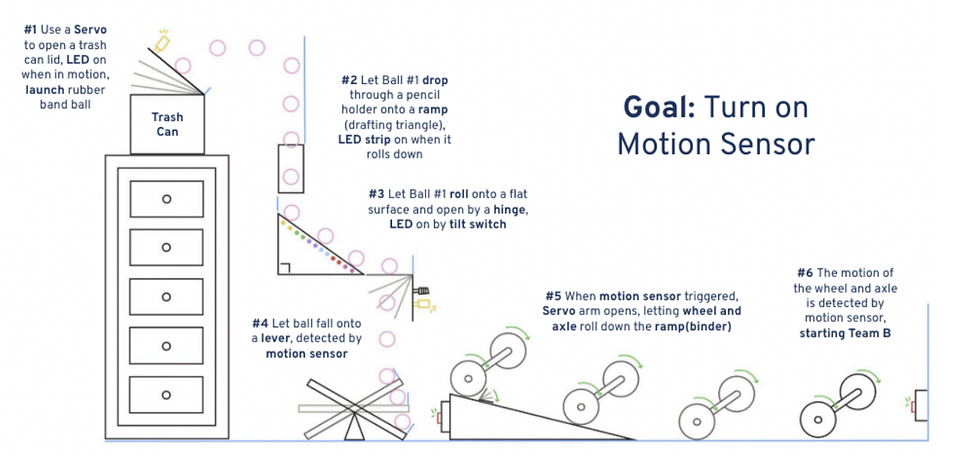
1) Rube Goldberg Machine (Final Project)
For our Cornerstone of Engineering I final project, my team and I designed and built one stage of a large class Rube Goldberg Machine. The goal was to complete a simple task in a playful, overly complex way while applying engineering design, electronics, and mechanical skills.
Each team was responsible for one themed stage that connected to the others, and we went through proposal, prototyping, testing, and final demonstration at the First-Year Engineering Expo.
All full documentation, design details, and media for this project are available on our shared team website, which is linked below.
2) Mechanisms (Skillbuilder)
Overview:
For my Mechanisms Skillbuilder, my partner and I modeled and built a mechanical system that converts rotary motion into linear motion based on Mechanism #166 (shown on the right) from 507 Mechanical Movements. Our goal was to understand and demonstrate how rotational input can generate controlled linear motion using multiple prototypes, from early hand-built models to a precise laser-cut version, while developing fabrication and CAD skills along the way.

What we Made:
Mechanism #166 converts rotary motion into linear motion. On one end, a rotating disk acts as the input. On the other, a fixed base supports a lever that generates linear movement. A connecting arm links the disk and the lever, transferring motion through a pivot joint.
Our team built three physical prototypes using different materials and fabrication methods:
-
Version 0: Notebook-paper mock-up (proof of concept)
-
Version 1 (Low-Fidelity Prototype): Cardboard model with paper and metal fasteners (functional prototype)
-
Final Version (Laser-Cut Prototype): Laser-cut model with precise dimensions and reduced friction
Each iteration improved stability, reduced friction, and refined the motion transfer between the disk and lever.
Version 0 (Paper Prototype):
The first version was made from two pieces of notebook paper and a few paper fasteners. This early model demonstrated the basic movement of the mechanism and helped us visualize how the connecting arm transferred motion between the rotating disk and lever. The material was too flexible to hold structure, but it allowed us to confirm that the concept worked.
Challenges and Observations:
-
Paper was too thin to support consistent motion
-
Fasteners worked well conceptually but lacked durability
-
Helped us confirm the geometry and proportions of the mechanism before using stronger material

Version 1 (Low-Fidelity Prototype):

The second version was built from cardboard and used both metal and paper fasteners. This gave the structure much more stiffness and made it possible to see consistent motion. However, friction between the layers caused some movement resistance.
Improvements Made:
-
Added small 1 cm × 1 cm cardboard squares between layers to reduce friction
-
Changed the connecting arm to a thinner cereal box cardboard to improve flexibility
-
Kept the same geometry as Version 0 but refined measurements for better alignment
Challenges:
-
Friction made the lever motion slightly rough
-
The material thickness made assembly less precise

Final Version (Laser-Cut Prototype):

The final version was designed in AutoCAD and laser-cut using a 16 × 12 in FYELIC template. This version matched our intended dimensions and had much smoother movement due to precise hole placement and reduced friction.
Key Design Changes:
Used laser-cut accuracy to improve fit between the lever and disk
Added low-friction tape on the fastener connecting the disk to the base
Adjusted the length ratio between the lever and disk for smoother motion
Technical Skills:
Drew all parts to scale in AutoCAD, including base, lever, connecting arm, and disk
Added a title block with team name, date, and project title
Verified geometry alignment for laser cutting


Reflection:
Through studying and building Mechanism #166, we learned the importance of sketching, planning, and iterating. We faced challenges with stability, friction, and material thickness, but found creative solutions like using layered spacers and paper fasteners to stabilize motion without a full workshop setup.
The final prototype successfully demonstrated rotary-to-linear motion and proved that the lever length should be proportional to the disk diameter for consistent motion. If we continued improving the design, we would use stronger materials like acrylic to further reduce wear over time.
This project strengthened our understanding of motion conversion, iterative design, and CAD fabrication. It also showed how small design details can make a large difference in mechanical performance.
3) Electronics (Skillbuilder)
Overview:
In this skillbuilder, I learned how to use an analog input sensor with a Raspberry Pi Pico. I chose a thermistor so I could measure temperature changes and convert them into meaningful digital data. My goals were to understand how the thermistor works, wire the circuit correctly, write code to calculate temperature, and teach others what I learned.
What I Made:
I built a working temperature sensing circuit using:
-
An NTC thermistor
-
A 10kΩ resistor functioning as a voltage divider
-
A Raspberry Pi Pico microcontroller
-
Python code to convert analog signals into temperature readings
I successfully created a functional system that detects temperature changes, reads them in real time, and converts the values into readable Celsius output.
Wiring Diagram:
Diagram explaining how the thermistor, resistor, and Raspberry Pi Pico are connected in a voltage-divider circuit.

Completed Circuit:
Full view of the finished temperature-sensing circuit on the breadboard.

Close-Up of Circuit:
Closer shot highlighting the thermistor, resistor, and wiring connections.

Python Code:
Main MicroPython program showing ADC readings, voltage conversion, and temperature calculation.

Pseudocode/Comments:
Code comments/pseudocode explaining what each part of the code does.

Process and Iterations:
Not everything worked smoothly at first. One challenge was finding a strong enough heat source to create noticeable changes in the readings. I tried using everyday objects around me, but the temperature barely changed. Eventually, I ordered a hair dryer, which worked perfectly and gave clear, responsive data changes.
Through troubleshooting, I learned:
-
How to confirm correct wiring and resistor placement
-
How real temperature data behaves and why calibration matters
-
How to communicate technical work visually and verbally
Integrated Circuit:
After presenting my thermistor project, I worked with a partner to integrate both of our electronic components into one interactive system. We combined my thermistor with their servo motor so the motor reacts to temperature changes.
Our combined system:
-
Read temperature using my thermistor circuit
-
Used my code to convert ADC data into Celsius
-
Triggered servo motion based on temperature thresholds
-
Included LEDs and timed movement behavior
This experience helped me understand how individual components can become part of a larger engineering system.


4) Takeapart (Skillbuilder)
Overview:
For this Skillbuilder, my partner and I completed a reverse-engineering project to better understand how everyday objects are designed, assembled, and function internally. We chose a handheld electric pencil sharpener from CVS (about $8) and took it apart to study the relationship between its electrical and mechanical components, identify the design decisions made by engineers, and communicate what we learned through documentation and reflection.


What we Did:
Working together, we:
-
Disassembled the sharpener using simple tools
-
Carefully removed components without damaging key parts when possible
-
Documented each step with photos
-
Organized and labeled internal components
-
Developed a problem statement about what we believe the designers were trying to solve
-
Reflected on the engineering choices and insights we gained
I still have the object, and it remains fully taken apart.
How it Works:
This project helped us understand how electrical and mechanical systems integrate to create one functioning device.
-
The battery holder has metal plates that conduct electrical current when batteries are inserted
-
Wires transfer power to the motor
-
The motor rotates gears
-
Gears adjust rotational speed and torque
-
The blade assembly spins to sharpen the pencil
-
The plastic casing protects users and contains all moving parts
-
A safety mechanism prevents sharpening unless a pencil is inserted


Problem Statement and User Need:
Plug-in sharpeners can be noisy, tied to specific classroom locations, and inconvenient when many students share a small number of sharpeners. Mechanical sharpeners are portable but can be slow and inconsistent.
This design appears to solve those problems by creating a sharpener that is:
-
Portable
-
Affordable
-
Safe
-
More quiet and stable than mechanical sharpeners
-
Battery powered so it works anywhere
-
Contained to reduce mess and hazard
The problem is that plug-in pencil sharpeners can be inconvenient to use at all times and places, especially if there are significantly more students in a classroom than sharpeners. They can also disrupt their classroom with their noise, and the time that it takes to wait for students to share sharpeners. This is an important problem because sharpening pencils is a very common and essential task for students in any classroom setting. Currently available designs require an outlet or are mechanical. Current solutions, however, are not both portable and quick to use at the same time. The users need a design that incorporates the electrical component of the plug-in style with the portability of a mechanical pencil sharpener. Our solution will sharpen pencils, collect shavings, and prevent jams while remaining affordable for the average student, lightweight, safe, battery-efficient, portable, and operating quietly.
Evidence of Design Decisions:
From the components, we can infer intentional engineering choices:
-
Plastic casing → affordable and lightweight for students
-
Battery-powered motor → portable and easier to use
-
Enclosed blade and gear system → safer and quieter
-
Built-in safety switch → prevents injury when no pencil is inserted


Process and Iterations:
What was challenging:
-
The outer casing was not screwed together
-
We had to bend and break part of it to access the interior
-
This showed that the sharpener was not designed for repair, highlighting tradeoffs in cost and longevity
What worked well:
-
We successfully removed and identified every component
-
We documented the entire process clearly
-
We were able to infer strong engineering reasoning from the object
What surprised us:
-
The motor was very small but produced enough torque to drive the gears consistently
-
The safety switch mechanism was well-designed and thoughtful
-
There was no cooling system, which raised interesting questions about heat buildup
Engineering Design Connections:
This project supported core elements of the engineering design process by:
-
Investigating how an engineered object works
-
Identifying functions, constraints, and user needs
-
Analyzing design tradeoffs
-
Learning from failure while opening the device
-
Reflecting on opportunities for improvement
C) Engineering Design Process:
Planning & Research
We studied campus layouts, simplified geometry for feasibility, and researched part availability through BrickLink.
Digital Modeling
All structures were modeled and rendered in BrickLink Studio before ordering materials. This ensured scale consistency and minimized purchasing errors.
Procurement & Budgeting
Used exported XML files to source parts from multiple sellers. Managed inventory tracking and order coordination.
Construction & Iteration
Built the model in stages, adjusting for missing pieces, structural weaknesses, and part substitutions when necessary.

3D modeled in BrickLink Studio prior to part procurement.
Displays stability analysis.


Procurement & Budgeting:

Proof of purchase from one of our many vendors.
Construction Timelapse:

Timelapse of our initial construction process.